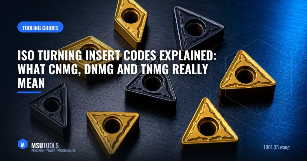
If you have ever stared at a box labelled CNMG120408 and wondered what those characters actually mean, you are not alone. The ISO 1832 designation system packs a complete description of an indexable insert into a short code. Once you can read it, selecting and re-ordering inserts becomes far faster — and far less error-prone.
The Code, Position by Position
A standard turning insert code such as C N M G 12 04 08 breaks down into seven positions:
| Position | Meaning | Example |
|---|---|---|
| 1 | Insert shape | C = 80° rhombic |
| 2 | Clearance (relief) angle | N = 0° (negative) |
| 3 | Tolerance class | M = medium |
| 4 | Type / chipbreaker & hole | G = hole + chipbreaker both sides |
| 5 | Cutting edge length | 12 = 12.7 mm |
| 6 | Thickness | 04 = 4.76 mm |
| 7 | Corner radius | 08 = 0.8 mm |
Position 1 — Shape
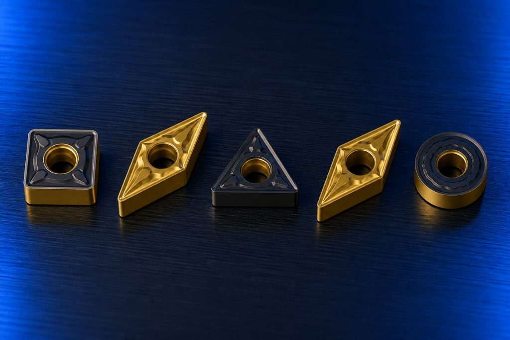
Shape governs the trade-off between edge strength and accessibility. Larger point angles are stronger but less able to reach into profiles.
- S — square (90°): strongest, four to eight edges, for roughing.
- C — 80° rhombic: the workhorse; handles both facing and longitudinal turning.
- W — 80° trigon: three strong edges, economical.
- D — 55° rhombic: good profiling access, weaker point.
- V — 35° rhombic: sharp profiling, most fragile.
- T — triangular (60°): versatile, three edges.
- R — round: maximum edge strength, ideal for copy turning.
Position 2 — Clearance Angle
N means 0° clearance — a negative insert. Negative inserts are double-sided, so you get twice the edges and a stronger cutting corner, but they push harder into the workpiece. P (11°) and C (7°) indicate positive inserts: single-sided, lower cutting forces, better for slender parts, thin walls and low-power machines.
Position 4 — Type
This letter is where most ordering mistakes happen. G has a hole and chipbreakers on both faces; M has a hole and single-sided chipbreaker; A has a hole but no chipbreaker; N has neither. A CNMG and a CNMA look similar in the catalogue but behave very differently in the cut — the CNMA has no chip control at all.
Positions 5–7 — The Numbers
The size digits follow a simple rule of thumb: cutting edge length in millimetres (rounded), thickness in millimetres (rounded), and corner radius in tenths of a millimetre. So 120408 = 12.7 mm edge, 4.76 mm thick, 0.8 mm radius.
Choosing the Corner Radius
Corner radius is the single most underrated parameter on the code. It controls surface finish, edge strength and the tendency to vibrate:
- Small radius (0.2–0.4 mm) — lower radial forces, better for slender parts and finishing light cuts.
- Medium radius (0.8 mm) — the default all-round choice for general turning.
- Large radius (1.2–1.6 mm) — stronger edge for heavy roughing, but needs a rigid setup or chatter appears.
A practical guideline: keep the depth of cut at or above the corner radius wherever possible. Cutting shallower than the radius makes the effective lead angle very small and drives the tool radially, which is a common cause of chatter on long shafts.
Grade Comes After the Code
The ISO code describes only the geometry. The carbide grade and coating — which decide how long the edge survives in your material — are specified separately by the manufacturer. Two inserts stamped CNMG120408 can have completely different lives in stainless steel if one is a steel (P) grade and the other a stainless (M) grade.
That is why we grade our carbide turning inserts to the ISO material groups: P for steel, M for stainless, K for cast iron, N for aluminium and non-ferrous, and S for titanium and superalloys.
A Quick Ordering Checklist
- Confirm the holder you have — it dictates shape, clearance and size.
- Choose negative for strength and economy, positive for low forces.
- Match the chipbreaker to your operation: finishing, medium or roughing.
- Select the corner radius against your depth of cut and finish requirement.
- Specify the grade for your workpiece material — not just the code.
Need Help Choosing?
MSU Tools manufactures the full range of solid carbide and indexable tooling discussed above. Tell us your material, machine and application, and our engineering team will recommend the optimal tool and grade — or design a custom solution to your drawing. Contact our engineers for a same-day technical reply.
Questions about this topic?
Our engineers are happy to advise on tools, grades and cutting parameters.