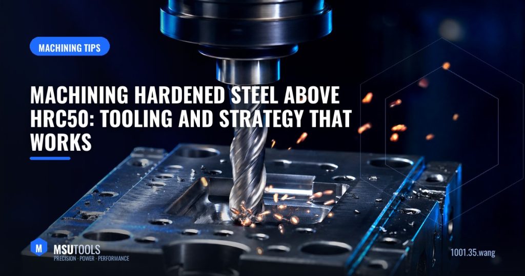
Hard milling — machining steel that has already been heat treated to HRC50 or above — lets mould and die makers skip the EDM and grinding steps and finish a cavity directly on the machining centre. The productivity gain is substantial, but the process is unforgiving. Rigidity, tool selection and toolpath discipline all have to be right at the same time.
Why Hardened Steel Is Different
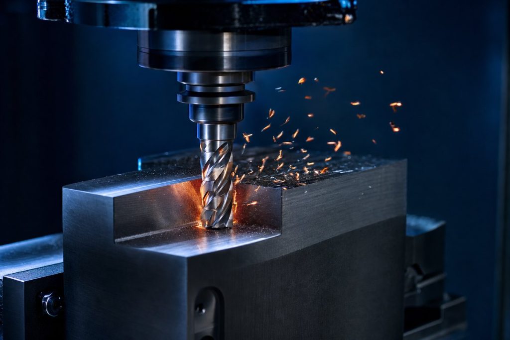
As hardness rises, cutting forces concentrate in a very small zone at the cutting edge and temperatures climb sharply. Above roughly HRC45 the chip formation mechanism changes — the material begins to shear in narrow bands and chips come off dark blue or straw-coloured, carrying most of the heat away. That is normal and desirable; it means heat is leaving in the chip rather than soaking into your tool and part.
Tool Selection
Substrate
Use ultra-fine grain carbide with relatively low cobalt content. Higher cobalt gives toughness but sacrifices the hot hardness you need above HRC55.
Coating
AlTiN or AlCrN. Their oxidation resistance above 900 °C is what keeps the edge intact. Standard TiN or TiCN will fail quickly.
Geometry
- Negative or near-neutral rake — a strong edge matters far more than a sharp one. Sharp positive geometry chips instantly in hardened material.
- More flutes — 4 to 6 flutes for finishing. Chip volume is low, so flute space is not the constraint; edge engagement and stability are.
- Short and stubby — use the shortest tool that reaches. Deflection is the enemy.
- Ball nose or corner radius — never a sharp corner. A corner radius distributes load and dramatically extends life.
Cutting Data Starting Points
| Hardness | Surface speed (m/min) | Radial engagement (ae) | Axial (ap), finishing |
|---|---|---|---|
| HRC45–50 | 120–180 | 2–5% of D | 0.1–0.3 mm |
| HRC50–55 | 100–150 | 2–5% of D | 0.1–0.2 mm |
| HRC55–60 | 80–120 | 1–3% of D | 0.05–0.15 mm |
| HRC60–65 | 50–90 | 1–3% of D | 0.05–0.1 mm |
Treat these as starting values and adjust to your machine’s rigidity. Note the pattern: as hardness rises, speed comes down and engagement gets lighter — but feed per tooth stays relatively constant. Feeding too lightly is a classic mistake; it causes rubbing instead of cutting, which work-hardens the surface and burns the edge.
Toolpath Strategy Matters as Much as the Tool
- Climb mill. Always, in hardened material. Conventional milling rubs before it cuts and destroys edges.
- Keep engagement constant. Use trochoidal or dynamic toolpaths for roughing so the tool never sees a sudden increase in engagement angle at a corner.
- Ramp or helix in. Never plunge straight down.
- Arc lead-ins and lead-outs. Entering the cut on an arc avoids the shock load of a straight-line entry.
- Leave even stock. Semi-finishing to a uniform 0.1–0.2 mm before the finishing pass is what makes a consistent finish possible.
Coolant: Usually Less Is More
This surprises people. In hard milling, flood coolant often reduces tool life. The edge is running hot by design, and every time it exits the cut and hits cold coolant it experiences thermal shock, which produces comb cracks perpendicular to the edge. Compressed air or minimum-quantity lubrication to clear chips is generally the better choice — the coating is designed to handle the heat.
Rigidity Is Non-Negotiable
A shrink-fit or high-precision hydraulic holder is worth more in hard milling than in any other operation. Runout above about 5 µm loads one flute far more than the others and the tool fails early. Check the spindle, the holder and the tool as one system.
Recognising Trouble
- Chipped edges — engagement too high, runout, or too-positive geometry.
- Rapid flank wear — speed too high, or the coating is wrong for the hardness.
- Comb cracks — thermal cycling; reduce or remove flood coolant.
- Poor finish with chatter marks — deflection; shorten the tool or reduce engagement.
Our SH and HRC-series solid carbide end mills are built specifically for this work: fine-grain substrate, AlCrN coating and reinforced core geometry for materials up to HRC65.
Need Help Choosing?
MSU Tools manufactures the full range of solid carbide and indexable tooling discussed above. Tell us your material, machine and application, and our engineering team will recommend the optimal tool and grade — or design a custom solution to your drawing. Contact our engineers for a same-day technical reply.
Questions about this topic?
Our engineers are happy to advise on tools, grades and cutting parameters.