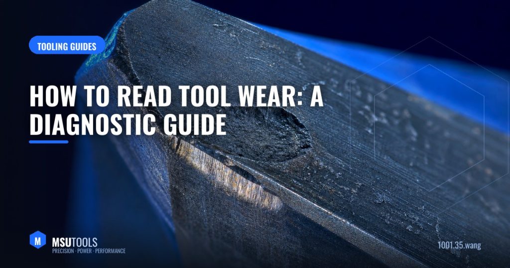
When a tool fails, most shops change it and carry on. But the worn edge is the best diagnostic data you will ever get: each wear pattern has a specific cause, and reading it correctly turns guesswork into a controlled process.
Flank Wear — The Good Kind
What it looks like: a uniform grey wear land along the flank below the cutting edge.
What it means: normal abrasive wear. This is what you want — predictable, gradual, and it lets you plan tool changes.
Act when: the wear land reaches roughly 0.3 mm for roughing or 0.15 mm for finishing. Beyond that, cutting forces and heat climb sharply and failure becomes sudden.
If it happens too fast: reduce cutting speed first — speed drives flank wear more than feed. Then check that the grade is right for the material.
Crater Wear
What it looks like: a hollow worn into the rake face just behind the edge.
What it means: chemical diffusion at high temperature — the chip is literally dissolving the tool as it slides.
Fix: reduce cutting speed, improve coolant delivery to the rake face, or move to a grade with a more diffusion-resistant coating (thicker CVD alumina layers help). A crater that breaks through to the edge causes sudden failure.
Built-Up Edge
What it looks like: workpiece material welded onto the cutting edge; the tool looks lumpy rather than worn.
What it means: cutting speed is too low for the material, or the rake face is too rough.
Fix: counter-intuitively, increase the cutting speed. Also use a sharper, more positive geometry and better lubrication. Common in aluminium, stainless and low-carbon steels.
Notch Wear
What it looks like: localised damage exactly at the depth-of-cut line, rather than along the whole edge.
What it means: the tool is cutting through a hardened or oxidised skin at that point — typical in stainless, superalloys and cast surfaces.
Fix: vary the depth of cut between passes so the notch does not concentrate at one height, use a larger lead angle to spread the load, or take a deeper cut that puts the line into softer material.
Thermal (Comb) Cracks
What it looks like: fine cracks perpendicular to the cutting edge, like teeth on a comb.
What it means: thermal cycling — the edge repeatedly heats and quenches.
Fix: in interrupted cuts, consider removing flood coolant entirely and letting the tool run hot but stable. Or use a tougher grade. This is one of the few cases where less coolant improves life.
Chipping and Edge Fracture
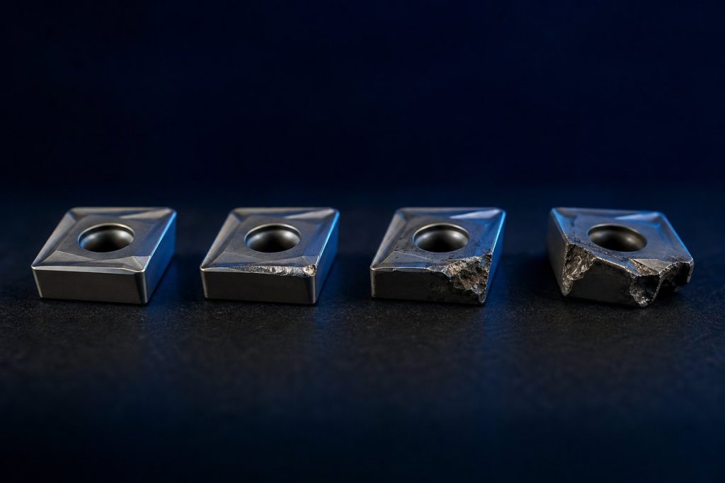
What it looks like: small pieces broken out of the edge, or a catastrophic break.
What it means: mechanical overload — excessive feed, unstable setup, vibration, hard inclusions, or a grade too brittle for the job.
Fix: improve rigidity first, reduce feed, use a tougher grade or a stronger edge preparation (a honed or T-land edge instead of a sharp one).
Plastic Deformation
What it looks like: the edge has slumped or bulged rather than worn away.
What it means: the carbide has softened — too much heat and pressure together.
Fix: reduce speed and feed, improve cooling, and select a grade with higher hot hardness (lower cobalt content).
A Practical Habit
Keep a cheap USB microscope by the machine and photograph edges when tools come off. Within a few weeks you will have a reference library for your own materials — and tool life becomes something you manage rather than something that happens to you.
If you are unsure what a wear pattern is telling you, send us a photo along with your material and cutting data — our engineering team will help you interpret it and recommend a grade.
Talk to Our Engineers
MSU Tools manufactures the full range of solid carbide and indexable tooling discussed here. Tell us your material, machine and application and we will recommend the optimal tool, grade and starting parameters — or design a custom tool to your drawing. Send us your requirement for a reply within one business day.
Questions about this topic?
Our engineers are happy to advise on tools, grades and cutting parameters.