
Face milling produces the flat datum surfaces almost every part depends on. The operation seems straightforward — but insert breakage on entry and inconsistent surface finish are common, and both come down to geometry decisions made before the cutter ever touches the part.
Lead Angle Changes Everything
Lead angle is the angle between the cutting edge and the machined surface. It determines how the cutting force splits between radial and axial directions, and how thick the chip is for a given feed.
| Lead angle | Chip thickness | Axial force | Best for |
|---|---|---|---|
| 90° | = feed per tooth | Low | Thin walls, weak fixtures, square shoulders |
| 45° | 0.71 × feed | Medium | General purpose — the default choice |
| 10° / round | Much thinner | High | Heavy roughing, hard materials, interrupted cuts |
The key insight: a smaller lead angle spreads the same feed over a longer cutting edge, so the chip is thinner and the edge is stronger. That means you can feed faster for the same chip load. The trade-off is higher axial force pushing down into the part — which needs a rigid setup.
Practical rule: 45° for general work; 90° when the part or fixture is flimsy or you need a true square shoulder; small lead or round inserts for heavy roughing in tough materials.
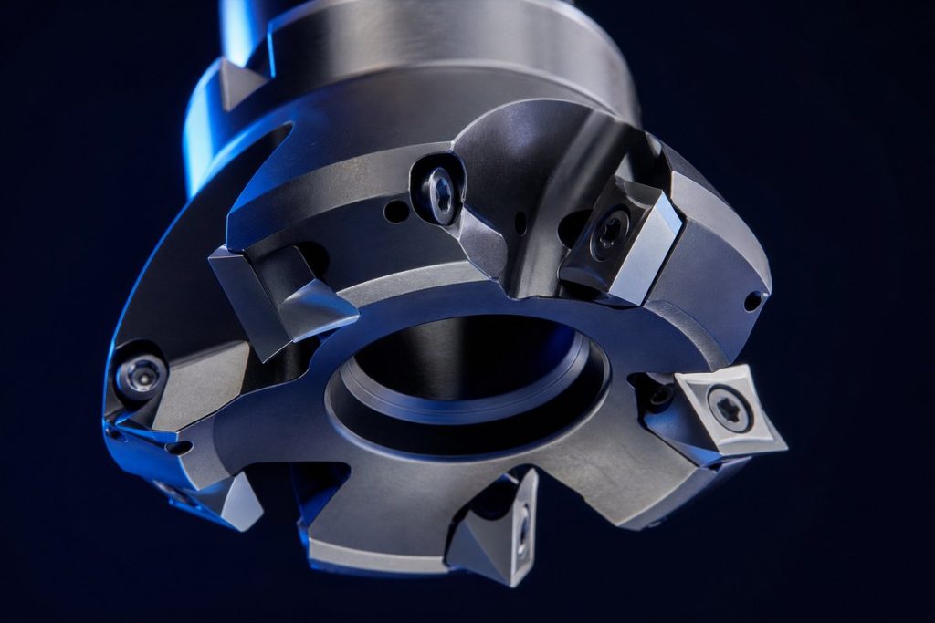
Positioning the Cutter
Where the cutter sits relative to the workpiece matters as much as the insert.
Never centre the cutter on the workpiece. With the cutter centred, each insert enters and exits at the thinnest possible chip — the worst case for edge life, and it maximises the tendency to vibrate.
Use a cutter 20–50% wider than the cut, offset so the centreline sits off to one side of the workpiece. Aim for roughly 70–80% engagement of the cutter diameter, with the centre of the cutter positioned outside the material edge.
This produces a favourable entry: the insert makes first contact away from its fragile tip, and the chip is thickest at entry and thinnest at exit.
Entry and Exit
Insert chipping in face milling is usually an entry or exit problem, not a wear problem.
- Best entry: the insert contacts the workpiece on its strong edge, not the tip corner. This is what proper cutter offset achieves.
- Reduce feed on entry and exit by around 50% if you are seeing chipped inserts on interrupted cuts.
- Roll into the cut with an arc rather than a straight plunge into the edge of the material.
- Avoid exiting over a sharp corner — the edge is unsupported at the moment it leaves, which is when it breaks.
Insert Grade and Geometry
- Steel (P): a coated grade with a medium chipbreaker handles the widest range.
- Cast iron (K): abrasion resistance matters most; run dry.
- Stainless (M): tough substrate, sharper positive geometry to prevent built-up edge.
- Aluminium (N): polished uncoated with high positive rake and a mirror-finish rake face.
For finishing passes, a single wiper insert set slightly proud produces a dramatically better surface finish at the same feed — often the cheapest way to eliminate a subsequent grinding operation.
Getting a Good Finish
- Check insert height. In a face mill, one insert sitting 0.02 mm proud does all the finishing work — and leaves visible marks. Verify seating and cleanliness.
- Climb mill for a better finish and less burr on the exit edge.
- Take a light finishing pass of 0.3–0.5 mm rather than trying to achieve size and finish in one heavy cut.
- Blow chips clear so the cutter does not re-cut them, which scars the surface.
Our indexable milling inserts — APMT, SEHT, RDMW and more — are available in grades for every ISO material group, with wiper options for finishing.
Talk to Our Engineers
MSU Tools manufactures the full range of solid carbide and indexable tooling discussed here. Tell us your material, machine and application and we will recommend the optimal tool, grade and starting parameters — or design a custom tool to your drawing. Send us your requirement for a reply within one business day.
Questions about this topic?
Our engineers are happy to advise on tools, grades and cutting parameters.