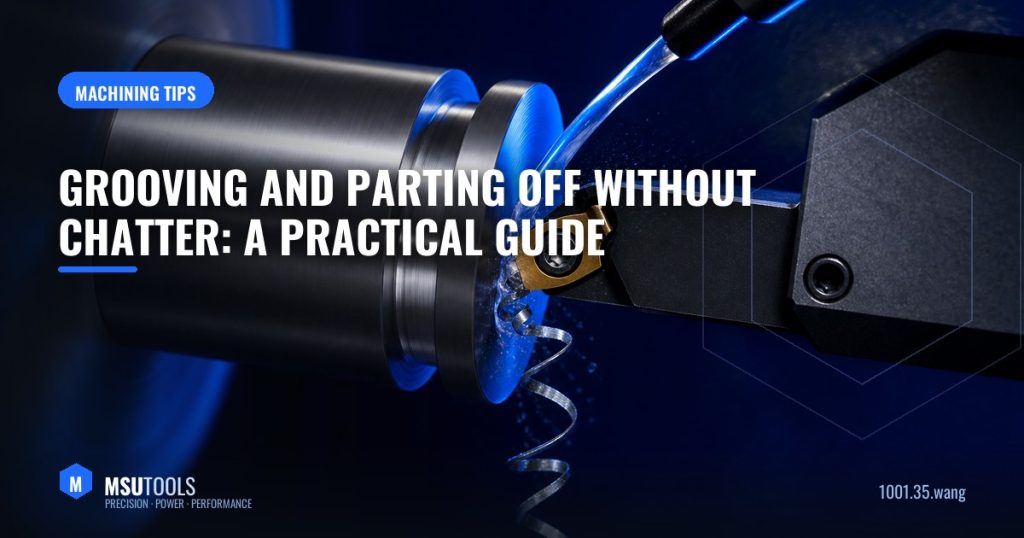
Parting off has a reputation for being the operation that goes wrong at the worst moment — at the end of a part, after all the value has already been added. The reasons are structural: a narrow blade reaching deep into the workpiece, cutting on a full-width edge, with the cutting speed falling towards zero as the tool approaches centre.
Understanding those constraints makes the operation predictable.
Why Parting Off Is Inherently Unstable
- The blade is thin. A 3 mm blade extending 25 mm has very little lateral stiffness.
- Full-width engagement. The entire cutting edge is in the cut, so there is no varying chip thickness to dampen vibration.
- Chip evacuation is confined. The chip must escape from a slot barely wider than itself.
- Surface speed falls to zero. At the centre, cutting speed becomes zero — a rubbing condition no coating survives.
Setup: Where Most Problems Are Solved
Minimise Overhang
This is the highest-leverage adjustment available. Set the blade to project only slightly more than the part radius plus a small clearance. Every extra millimetre of overhang reduces stiffness disproportionately — halving overhang increases stiffness roughly eightfold.
Get the Centre Height Right
Centre height tolerance in parting is ±0.1 mm, and it matters more than in any other turning operation:
- Above centre — clearance is lost, the tool rubs, and a pip is left on the part.
- Below centre — the tool is drawn into the cut, and the remaining pip breaks off, often taking the insert with it.
Blade Square to the Axis
Any angular error makes the blade rub on one side of the groove, generating heat and pushing the tool off line.
Cutting Data
| Material | Speed (m/min) | Feed (mm/rev) |
|---|---|---|
| Low carbon steel | 150–250 | 0.08–0.18 |
| Alloy steel | 120–180 | 0.06–0.15 |
| Stainless steel | 80–140 | 0.05–0.12 |
| Cast iron | 100–160 | 0.10–0.20 |
| Aluminium | 300–600 | 0.10–0.25 |
Feed is your friend. The instinct when chatter starts is to slow the feed — which is exactly wrong. A light feed produces a thin chip that rubs and encourages vibration. Increasing feed usually stabilises the cut. If chatter persists, reduce speed, not feed.
Approaching Centre
Because surface speed drops to zero at the centre, constant surface speed (G96) must be capped with a spindle speed limit (G50) — otherwise the control will command impossible RPM near the middle. In practice:
- Set a sensible maximum spindle speed.
- At roughly 2 mm from centre, either reduce feed by about 25% or switch to constant RPM (G97).
- For bar work, parting fully through is normal; for larger parts, consider parting to a small remaining diameter and finishing separately.
Coolant Placement
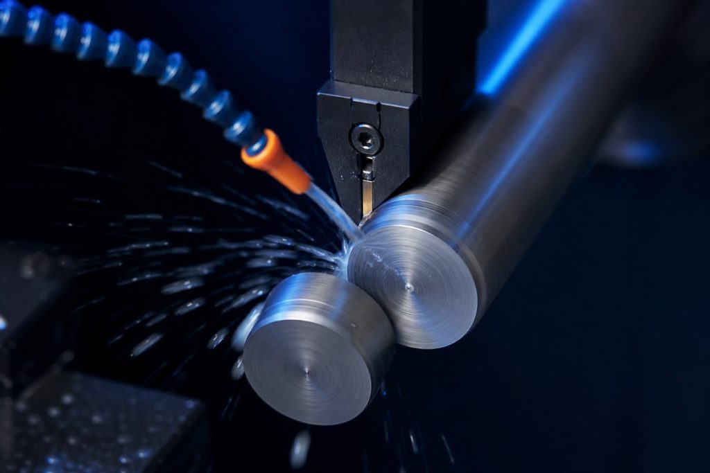
Coolant aimed at the general area of the tool does very little in parting. It needs to reach the cutting edge inside the groove. Blades with internal coolant channels that deliver fluid directly to the edge transform this operation, particularly in stainless steel where chip welding is the main failure mode. Where high-pressure coolant is available, 30–70 bar makes a dramatic difference to chip evacuation.
Insert Width and Geometry
Use the narrowest insert that will do the job safely — it reduces cutting force, material waste and power draw. As a guide, blade width of roughly 0.1× the workpiece diameter plus 1 mm is a reasonable starting point.
Insert geometry choice affects the parted face:
- Neutral — leaves a small pip on both sides; strongest edge.
- Left- or right-hand angled (5–15°) — leaves a clean face on one side and the pip on the offcut. Ideal when the parted face is a finished surface.
Troubleshooting
- Chatter — reduce overhang first, then increase feed, then reduce speed.
- Insert breaks near centre — centre height low, or speed not capped approaching centre.
- Pip left on the part — tool above centre.
- Tapered groove walls — blade not square, or excessive deflection.
- Chips jamming in the groove — insufficient coolant pressure or wrong chipbreaker.
Our MGMN, MGGN and MRMN grooving and parting inserts are available in widths from 1.5 mm upward, in grades matched to each ISO material group.
Need Help Choosing?
MSU Tools manufactures the full range of solid carbide and indexable tooling discussed above. Tell us your material, machine and application, and our engineering team will recommend the optimal tool and grade — or design a custom solution to your drawing. Contact our engineers for a same-day technical reply.
Questions about this topic?
Our engineers are happy to advise on tools, grades and cutting parameters.